multi usb port circuit diagram Wiring Diagram
USB Pinout Diagram. A USB cable's wiring and connections can be visualized with the help of a pinout diagram. Type-A, Type-B, Mini-USB, Micro-USB, and USB-C are just a few of the varieties of USB connectors available. Pinout diagrams, which display the configuration and functionality of connectors, are specific to each variety.
Usb A To Usb C Wiring Diagram
The USB A pinout refers to the specific arrangement of pins within the Universal Serial Bus Type A connector. Understanding a USB A diagram is essential for connecting devices, troubleshooting, and even crafting custom cable solutions for specific needs. Structure of USB A Pinout. The USB A pinout consists of four pins, each with a unique function:

Usb A Wiring Diagram
To understand the wire diagram of a USB A connector, it is important to know the different types of wires and their functions. Typically, a USB A connector consists of four wires: two power wires (VCC and GND) and two data wires (D+ and D-). The VCC wire carries the power supply voltage, while the GND wire is the ground reference for the circuit.
Usb A To Usb A Wiring Diagram Fab Base
USB cables come with five different basic types of USB connector: types A, B, micro B, mini B, and C.The mini connector is common on older non-Apple mobile phones and other portables. However, the USB micro has largely replaced the mini in recent years, and USB-C may soon replace the micro.. The mini connector is compatible with the first and second-generation USB standard, but was replaced by.
Usb A To Usb A Cable Wiring Diagram Artsied
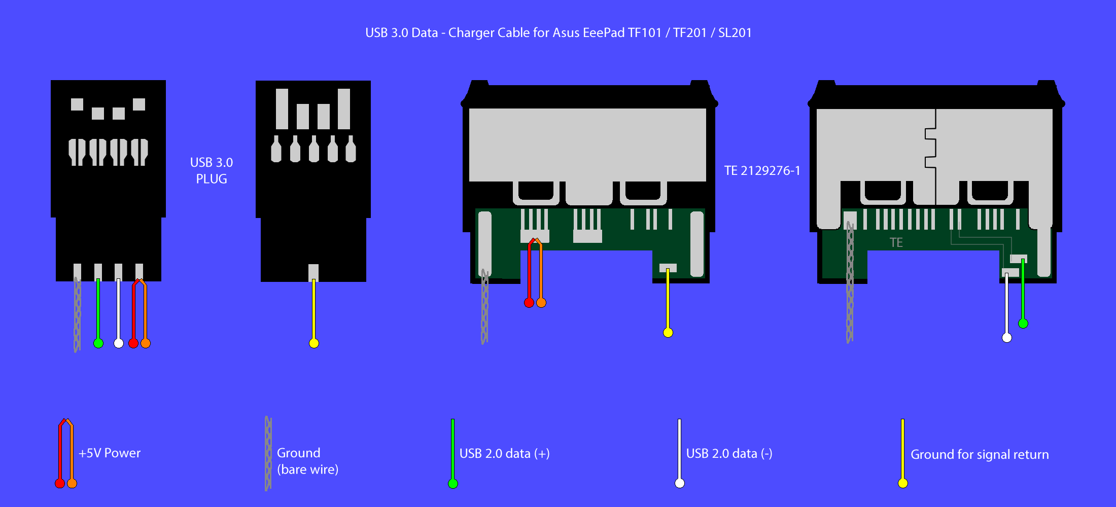
The USB pinout can be divided into two parts: USB Connector Pinout and USB port Pinout. The connector here refers to the device that goes into the USB port.. The pinout diagrams of the superspeed versions of different USB types are described in the following section. USB Type A 3.0 and Type B 3.0. As discussed above, the normal Type A and.

Usb Cable Wiring Color Code
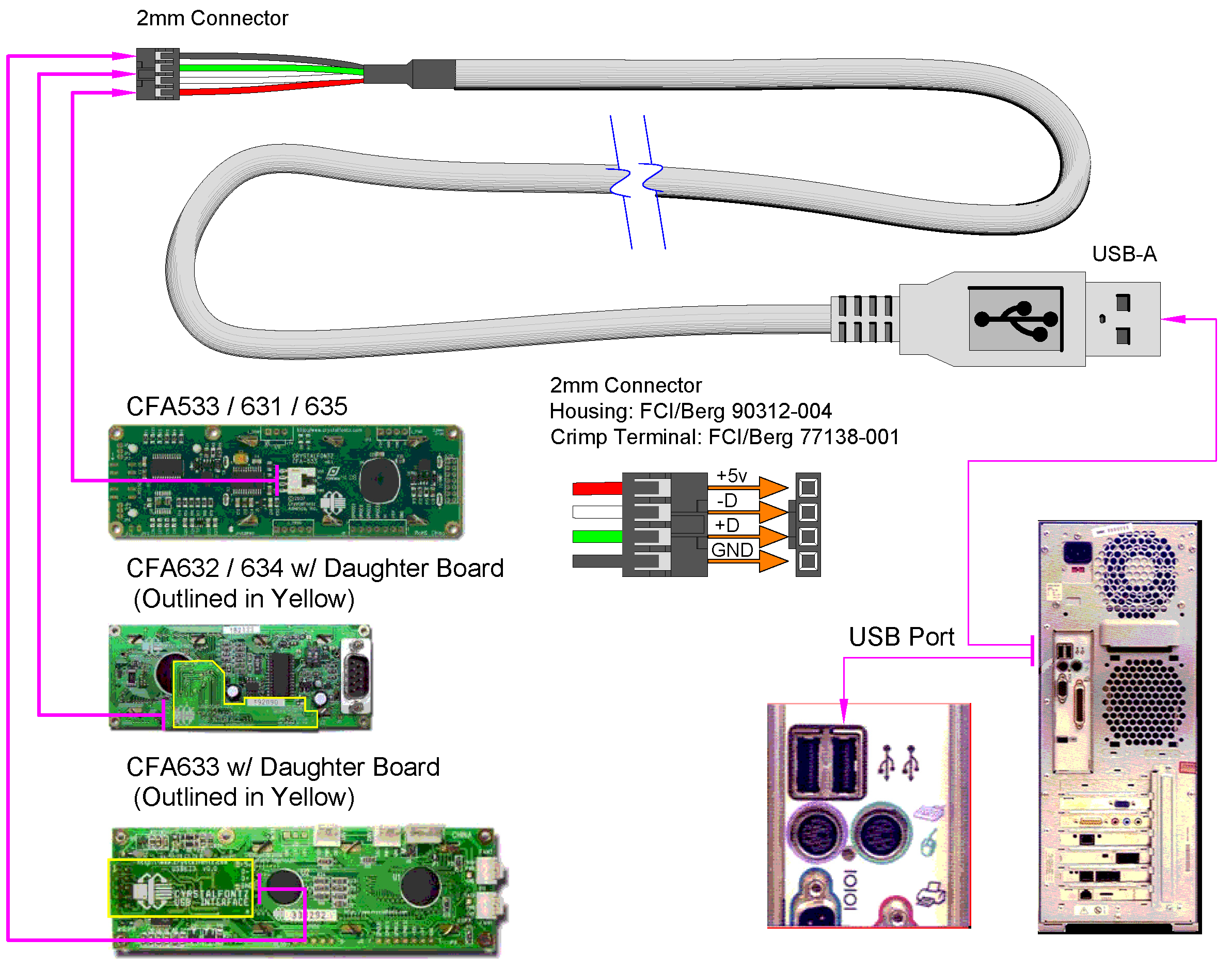
USB A, B 2.0 and 3.0 Cable Pinout. The USB cable provides four pathways- two power conductors and two twisted signal conductors. The USB device that uses full speed bandwidth devices must have a twisted pair D+ and D- conductors. The data is transferred through the D+ and D- connectors while Vbus and Gnd connectors provide power to the USB device.

Usb Wiring Schematic
USB A Wire Diagram: Understanding the Components and Connections. USB A wire diagram is a visual representation of the wiring components and connections found in a USB Type-A connector. USB Type-A connectors are commonly used in computer systems and electronic devices to connect peripherals such as keyboards, mice, printers, and external.

USB pinout, wiring and how it works!
USB wiring diagram comes in handy when USB port or connector either of them malfunctions or completely out of order, also for engineers and hobbyist who wants to explore the electronics wiring practically. These cables breakdown occurs due to excessive use of USB wire (here excessive use means repetitive use of wire or connecting port in a.

Usb Plug Wiring Diagram
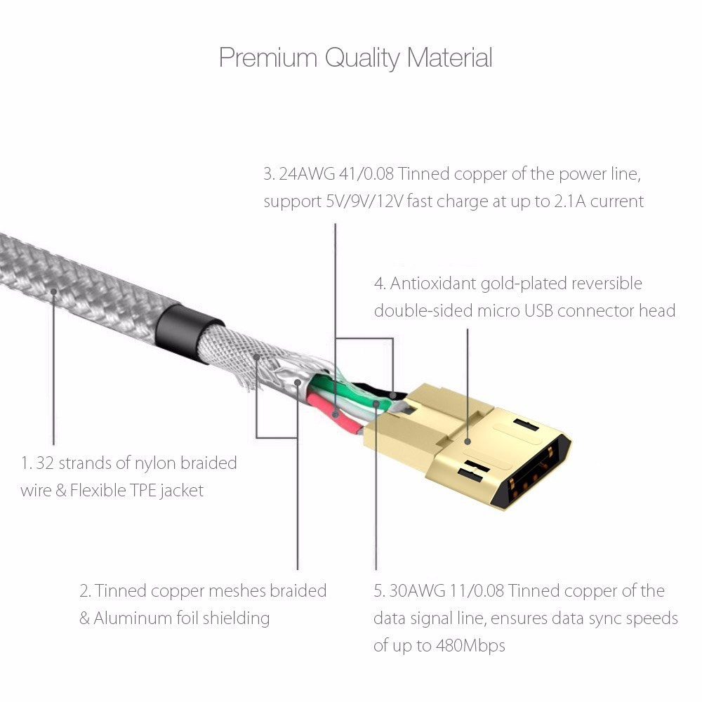
USB 3.0 connectors contain legacy pins to interface to USB 2.0 devices, and a new set of pins for USB 3.0 connectivity (both sets reside in the same connector). USB Cable. USB cable has four conductors, two for power and two for data. The data wires are 28 AWG, the power wires are 20 to 28 AWG. The power cores are un-twisted and the data lines.

Wiring Diagram For Usb Cable
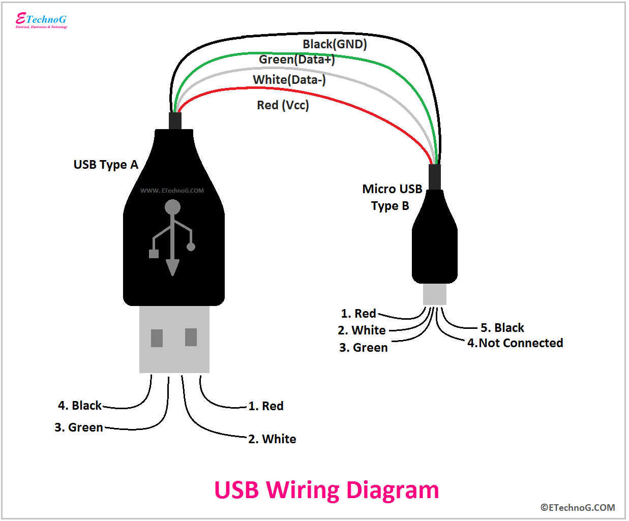
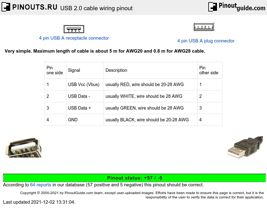
Pinout of USB cable schematic and layout of 4 pin USB A / USB B / mini-USB jack connector and 4 pin USB A or USB B plug connectorVery simple. Maximum length of cable is about 5 m for AWG20 and 0.8 m for AWG28 cable.. USB Vcc (Vbus) usually RED, wire should be 20-28 AWG: 1: 2: USB Data - usually WHITE, wire should be 28 AWG: 2: 3: USB Data.

check your front panel usb ports with multimeter
The USB wiring diagram on a motherboard typically includes information about the USB version supported (such as USB 2.0 or USB 3.0), the pin layout for each USB port, and the power and data connections. The diagram may also indicate which ports are capable of charging devices and which ports are for data transfer only.
USB cable wiring pinout diagram
Understanding USB Pinouts Diagram. USB pinouts diagram is a graphical representation of the different pins and their functions in a USB connector. It is essential to understand the pinouts diagram when working with USB cables or devices, as it helps in correctly connecting the wires and ensuring proper functionality. 1.

Usb Wiring Diagram Printable
Micro USB Pinout Diagrams Looking at the micro connector on a cable, all generations have pins numbered 1-4, ascending, from left to right on the main trapezoid. Third generation connectors have pins 6-10, ascending, from left to right, on the added side rectangle.
USB Wiring Diagram A Complete Tutorial EdrawMax (2023)
2. USB Wiring Diagram: Understanding the Pins. USB connectors have multiple pins that serve different purposes. The most common USB connectors are Type-A and Type-B. Type-A is typically used on host devices like computers, while Type-B is commonly found on peripheral devices.
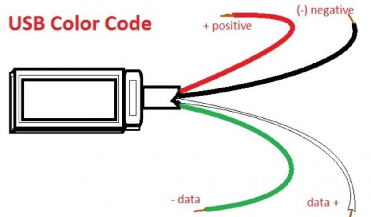
USB wiring and color code hubpages
USB-C Connector. The USB Type-C is the USB specification that's slowly replacing the USB-B. It's a tiny 24-pin reversible plug that works for USB cabling and devices. Type-C USBs can serve as connectors for both hosts and devices. Plus, you can find Type-C USBs in most recent mobile devices. USB-C Connector Pinout

Wiring Diagram For Usb Connector
USB wiring diagrams typically include information about the different pin numbers, wire colors, and functions of each wire. For example, in a USB Type-A connector, pin 1 is usually the +5V power supply, pin 2 is the Data- signal, pin 3 is the Data+ signal, and pin 4 is the ground.